4. Describing measurements#
import numpy as np
import pandas as pd

import weldx
import weldx.measurement as msm
import weldx.transformations as tf
from weldx import Q_
from weldx.welding.util import sine
4.1. Overview#
In this short example we use welding voltage and current measurements to show how to describe and store measurements with associated measurement chains. This includes describing the measurement equipment and its metadata, describing all the relevant transformation steps from raw-data to the final output and the data itself. The final result is a MeasurementChain that should be easy to follow and represent the complete data processing pipeline.
4.2. Generating the measurement data#
We start by creating some “dummy” datasets that represent the current and voltage measurements. In a real application, these would be the datasets that we would copy from our measurement equipment (e.g. downloaded form a HKS-WeldQAS, oscilloscope or similar systems). The values in this dataset represent the actual physical current and voltage data in A and V.
time = pd.timedelta_range(start="0s", end="10s", freq="1ms")
I_ts = sine(f=Q_(10, "1/s"), amp=Q_(20, "A"), bias=Q_(300, "A"))
I = I_ts.interp_time(time)  # noqa: E741

current_data = weldx.TimeSeries(data=I.data, time=time)
current_data
<TimeSeries>
Time:
	Time:
TimedeltaIndex([       '0 days 00:00:00', '0 days 00:00:00.001000',
                '0 days 00:00:00.002000', '0 days 00:00:00.003000',
                '0 days 00:00:00.004000', '0 days 00:00:00.005000',
                '0 days 00:00:00.006000', '0 days 00:00:00.007000',
                '0 days 00:00:00.008000', '0 days 00:00:00.009000',
                ...
                '0 days 00:00:09.991000', '0 days 00:00:09.992000',
                '0 days 00:00:09.993000', '0 days 00:00:09.994000',
                '0 days 00:00:09.995000', '0 days 00:00:09.996000',
                '0 days 00:00:09.997000', '0 days 00:00:09.998000',
                '0 days 00:00:09.999000',        '0 days 00:00:10'],
               dtype='timedelta64[ns]', length=10001, freq=None)
Values:
	[300.         301.25581039 302.50666467 ... 297.49333533 298.74418961
 300.        ]
Interpolation:
	step
Units:
	A
U_ts = sine(f=Q_(10, "1/s"), amp=Q_(3, "V"), bias=Q_(40, "V"), phase=Q_(0.1, "rad"))
U = U_ts.interp_time(time)

voltage_data = weldx.TimeSeries(data=U.data, time=time)
voltage_data
<TimeSeries>
Time:
	Time:
TimedeltaIndex([       '0 days 00:00:00', '0 days 00:00:00.001000',
                '0 days 00:00:00.002000', '0 days 00:00:00.003000',
                '0 days 00:00:00.004000', '0 days 00:00:00.005000',
                '0 days 00:00:00.006000', '0 days 00:00:00.007000',
                '0 days 00:00:00.008000', '0 days 00:00:00.009000',
                ...
                '0 days 00:00:09.991000', '0 days 00:00:09.992000',
                '0 days 00:00:09.993000', '0 days 00:00:09.994000',
                '0 days 00:00:09.995000', '0 days 00:00:09.996000',
                '0 days 00:00:09.997000', '0 days 00:00:09.998000',
                '0 days 00:00:09.999000',        '0 days 00:00:10'],
               dtype='timedelta64[ns]', length=10001, freq=None)
Values:
	[40.29950025 40.48633974 40.67125987 ... 39.92301733 40.11147877
 40.29950025]
Interpolation:
	step
Units:
	V
It is important to note the type and structure of the current_data and voltage_data datasets:
they are created as
TimeSeriesthe data itself is a
pint.Quantityi.e. a numpy array with associated unit. For the current measurement this isampere, the voltage is given involt. Using quantities is an important core concept of measurements !each
TimeSerieshas atimedimension and coordinate using numpy datetime formats.
4.3. Equipment and Software#
Next, let’s define some equipment and software that is used throughout the measurement chain. We will use and add more information to these objects later. In out example, two types of hardware equipment are used:
The
HKS P1000-S3is a standard welding process sensor that detects the welding voltage and current using a hall sensor. The result is output as two analog signals scaled to +/- 10 V.The
Beckhoff ELM3002-0000is a fieldbus AD-converter terminal that picks up the analog signals of the HKS Sensor and transmits them digitally to the control software.
The final piece involved in the measurement chain is the Software used to record, scale and save both the welding current and voltage measurements. We define the software version and name used during the example using built-in ASDF types.
HKS_sensor = msm.MeasurementEquipment(name="HKS P1000-S3")

BH_ELM = msm.MeasurementEquipment(name="Beckhoff ELM3002-0000")
from asdf.tags.core import Software

twincat_scope = Software(name="Beckhoff TwinCAT ScopeView", version="3.4.3143")
4.4. Defining a measurement chain: current measurement#
Now we define the missing elements of our measurement chain and bundle everything together. A core concept of the chain are signals that go in and out of transformations which define mathematical operations of the signals, forming the chain.
Each measurement chain starts with a source signal. This is the point where our physical process or quantity is initially detected by a sensor. Since every MeasurementChain needs at least a source, we need to provide the corresponding information when creating an instance of this class.
As shown in the tutorial about the measurement chain class, there are several ways to do this.
Because we have already defined our source equipment, we will add the SignalSource to the MeasurementEquipment and use it to create our MeasurementChain.
The necessary parameters to create the SignalSource are its name, the output_signal and the source_error representing the uncertainty attached to the signal source.
For our current measurement, the source outputs an analog Signal of unit V.
According to the spec sheet of the sensor the measurement error in this initial step is 0.1 % which can be documented using the Error property (again using quantities).
current_source = msm.SignalSource(
    name="Current sensor",
    error=msm.Error(Q_(0.1, "percent")),
    output_signal=msm.Signal(signal_type="analog", units="V"),
)

HKS_sensor.sources.append(current_source)
Now we can create the current measurement chain. Since there is no recording of this measurement we do not provide any data.
welding_current_chain = msm.MeasurementChain.from_equipment(
    name="welding current measurement chain",
    equipment=HKS_sensor,
)
The next step in the chain is picking up the analog voltage signal from our source with the Beckhoff AD converter terminal which transform the signal into an internal signed integer value. The formula describing this linear transformation with input x is
a * x + b
32768 / (10 V) * x  + 0
We express this signal transformation as an analytical formula. Based on the above formula we also define the static parameters a and b in the MathematicalExpression. Note that we use quantities here as well!
Since our result is a dimensionless integer a has the unit 1/V and b is dimensionless which we indicate with "".
from weldx.tags.core.mathematical_expression import MathematicalExpression

current_AD_func = MathematicalExpression(
    expression="a * x + b", parameters=dict(a=Q_(32768.0 / 10.0, "1/V"), b=Q_(0.0, ""))
)
Now that we have the transform function we can define our SignalTransformation.
Our new Transformation outputs a new dimensionless signal of type digital.
The Beckhoff AD converter lists the measurement Error at 0.01 %.
current_AD_transform = msm.SignalTransformation(
    name="AD current",
    func=current_AD_func,
    type_transformation="AD",
    error=msm.Error(Q_(0.01, "percent")),
)
We add the transformation to our MeasurementEquipment representing the Beckhoff AD converter.
BH_ELM.transformations.append(current_AD_transform)
Next we use the equipment to add the transformation to the measurement chain.
welding_current_chain.add_transformation_from_equipment(BH_ELM)
Similar to the AD conversion, we add the final step of our signal processing chain: digitally converting the signal to the final physical representation of the welding current. The current calibration formula from our integer values to the real current values is as follows:
1000 A / 32768 * x + 0 A
Put into a new sympy expression:
# define current output calibration expression and transformation
current_calib_func = MathematicalExpression(
    "a * x + b", parameters=dict(a=Q_(1000.0 / 32768.0, "A"), b=Q_(0.0, "A"))
)
We create the final transformation step:
the output signal is our final current measurement representation
we add the our measurement data to this signal !
we add the software as a meta field to the signal transformation, since the
Softwareclass currently does not provide the option to store transformations and therefore can’t be linked automatically by theMeasurementChain
current_calib_transform = msm.SignalTransformation(
    name="calibration current",
    error=msm.Error(0.0),
    func=current_calib_func,
    meta=twincat_scope,
)

welding_current_chain.add_transformation(
    transformation=current_calib_transform, data=current_data
)
Now that our MeasurementChain is complete, we can visualize it using its plot function.
welding_current_chain.plot()
<Axes: title={'center': 'welding current measurement chain'}>
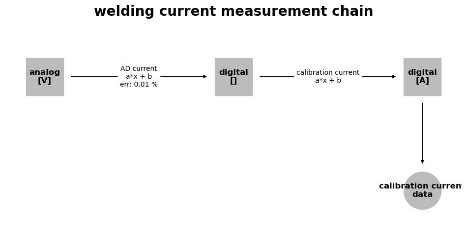
Finally the Measurement is our measurement chain with another link to the data.
welding_current = msm.Measurement(
    name="welding current measurement",
    data=[current_data],
    measurement_chain=welding_current_chain,
)
4.5. voltage measurement#
We follow the same procedure described in the current measurement here :-)
voltage_source = msm.SignalSource(
name="Voltage sensor",
error=msm.Error(Q_(0.1, "percent")),
output_signal=msm.Signal(signal_type="analog", units="V"),
)
HKS_sensor.sources.append(voltage_source)
welding_voltage_chain = msm.MeasurementChain.from_equipment(
name="welding voltage measurement",
equipment=HKS_sensor,
source_name="Voltage sensor",
)
voltage_ad_func = MathematicalExpression(
"a * x + b", parameters=dict(a=Q_(32768.0 / 10.0, "1/V"), b=Q_(0.0, ""))
)
voltage_AD_transform = msm.SignalTransformation(
name="AD voltage",
error=msm.Error(Q_(0.01, "percent")),
func=voltage_ad_func,
type_transformation="AD",
)
BH_ELM.transformations.append(voltage_AD_transform)
welding_voltage_chain.add_transformation_from_equipment(
equipment=BH_ELM, transformation_name="AD voltage"
)
# define voltage output calibration expression and transformation
voltage_calib_func = MathematicalExpression(
expression="a * x + b", parameters=dict(a=Q_(100.0 / 32768.0, "V"), b=Q_(0.0, "V"))
)
voltage_calib_transform = msm.SignalTransformation(
name="calibration voltage",
error=msm.Error(0.0),
func=voltage_calib_func,
meta=twincat_scope,
)
welding_voltage_chain.add_transformation(
transformation=voltage_calib_transform,
data=voltage_data,
)
welding_voltage = msm.Measurement(
name="welding voltage measurement",
data=[voltage_data],
measurement_chain=welding_voltage_chain,
)
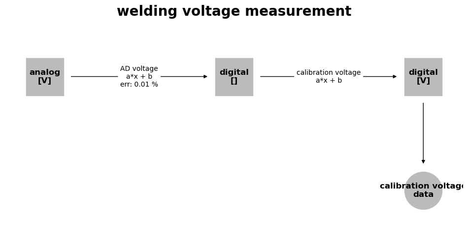
welding_voltage_chain.plot()
<Axes: title={'center': 'welding voltage measurement'}>
4.6. Coordinate Systems#
Most data does not make much sense without being able to determine where it was recorded in relation to a specimen or other measurement spots. Therefore, we define coordinate systems and their orientations towards each other. The basic principles are already explained in the transformation tutorials, so we will just define some coordinate systems without further explanation. To keep things simple, no time dependent coordinates are considered.
lcs_specimen_in_root = tf.LocalCoordinateSystem(
    coordinates=Q_(np.asarray([100, 75, 0]), "mm")
)
lcs_flange_in_root = tf.LocalCoordinateSystem(
    orientation=tf.WXRotation.from_euler("x", np.pi / 2).as_matrix(),
    coordinates=Q_(np.asarray([115, -10, 140]), "mm"),
)
lcs_torch_in_flange = tf.LocalCoordinateSystem(
    coordinates=Q_(np.asarray([100, 75, 0]), "mm")
)

coordinate_systems = tf.CoordinateSystemManager("root")
coordinate_systems.add_cs("specimen", "root", lcs_specimen_in_root)
coordinate_systems.add_cs("flange", "root", lcs_flange_in_root)
coordinate_systems.add_cs("torch", "flange", lcs_torch_in_flange)
TODO: Connect data to coordinate systems
4.7. Writing to ASDF#
Once we have defined all object we can write them to an ASDF file. To make the file easier to read we place some elements earlier in the tree.
equipment = [HKS_sensor, BH_ELM]
measurement_data = [current_data, voltage_data]
measurements = [welding_current, welding_voltage]

tree = {
    # "coordinate_systems": coordinate_systems,
    "equipment": equipment,
    "data": measurement_data,
    "measurements": measurements,
}
file = weldx.WeldxFile(tree=tree, mode="rw")
file.header()
#ASDF 1.0.0
#ASDF_STANDARD 1.5.0
%YAML 1.1
%TAG ! tag:stsci.edu:asdf/
%TAG !weldx! asdf://weldx.bam.de/weldx/tags/
--- !core/asdf-1.1.0
asdf_library: !core/software-1.0.0 {author: The ASDF Developers, homepage: 'http://github.com/asdf-format/asdf',
  name: asdf, version: 2.15.1}
history:
  extensions:
  - !core/extension_metadata-1.0.0
    extension_class: asdf.extension.BuiltinExtension
    software: !core/software-1.0.0 {name: asdf, version: 2.15.1}
  - !core/extension_metadata-1.0.0
    extension_class: weldx.asdf.extension.WeldxExtension
    extension_uri: asdf://weldx.bam.de/weldx/extensions/weldx-0.1.2
    software: !core/software-1.0.0 {name: weldx, version: 0.7.4.dev6+g2331a004c.d20260507}
data:
- &id005 !weldx!core/time_series-0.1.1
  &id001 values: &id002 !core/ndarray-1.0.0
    data: []
    datatype: float64
    shape: [10001]
  time: !weldx!time/time-0.1.0
    values: !weldx!time/timedeltaindex-0.1.0 {start: !weldx!time/timedelta-0.1.0 P0DT0H0M0S,
      end: !weldx!time/timedelta-0.1.0 P0DT0H0M10S, freq: ms, min: !weldx!time/timedelta-0.1.0 P0DT0H0M0S,
      max: !weldx!time/timedelta-0.1.0 P0DT0H0M10S}
  units: !weldx!units/units-0.1.0 ampere
  shape: [10001]
  interpolation: step
  *id001 : *id002
- &id011 !weldx!core/time_series-0.1.1
  &id003 values: &id004 !core/ndarray-1.0.0
    data: []
    datatype: float64
    shape: [10001]
  time: !weldx!time/time-0.1.0
    values: !weldx!time/timedeltaindex-0.1.0 {start: !weldx!time/timedelta-0.1.0 P0DT0H0M0S,
      end: !weldx!time/timedelta-0.1.0 P0DT0H0M10S, freq: ms, min: !weldx!time/timedelta-0.1.0 P0DT0H0M0S,
      max: !weldx!time/timedelta-0.1.0 P0DT0H0M10S}
  units: !weldx!units/units-0.1.0 volt
  shape: [10001]
  interpolation: step
  *id003 : *id004
equipment:
- &id010 !weldx!equipment/measurement_equipment-0.1.0
  name: HKS P1000-S3
  sources:
  - &id006 !weldx!measurement/source-0.1.0
    name: Current sensor
    output_signal: &id007 !weldx!measurement/signal-0.1.0
      signal_type: analog
      units: !weldx!units/units-0.1.0 volt
    error: !weldx!measurement/error-0.1.0
      deviation: !weldx!units/quantity-0.1.0 {value: 0.1, units: !weldx!units/units-0.1.0 percent}
  - &id012 !weldx!measurement/source-0.1.0
    name: Voltage sensor
    output_signal: &id013 !weldx!measurement/signal-0.1.0
      signal_type: analog
      units: !weldx!units/units-0.1.0 volt
    error: !weldx!measurement/error-0.1.0
      deviation: !weldx!units/quantity-0.1.0 {value: 0.1, units: !weldx!units/units-0.1.0 percent}
  transformations: []
- &id008 !weldx!equipment/measurement_equipment-0.1.0
  name: Beckhoff ELM3002-0000
  sources: []
  transformations:
  - &id009 !weldx!measurement/signal_transformation-0.1.0
    name: AD current
    error: !weldx!measurement/error-0.1.0
      deviation: !weldx!units/quantity-0.1.0 {value: 0.01, units: !weldx!units/units-0.1.0 percent}
    func: !weldx!core/mathematical_expression-0.1.0
      expression: a*x + b
      parameters:
        a: !weldx!units/quantity-0.1.0 {value: 3276.8, units: !weldx!units/units-0.1.0 1
            / volt}
        b: !weldx!units/quantity-0.1.0 {value: 0.0, units: !weldx!units/units-0.1.0 dimensionless}
    type_transformation: AD
  - &id014 !weldx!measurement/signal_transformation-0.1.0
    name: AD voltage
    error: !weldx!measurement/error-0.1.0
      deviation: !weldx!units/quantity-0.1.0 {value: 0.01, units: !weldx!units/units-0.1.0 percent}
    func: !weldx!core/mathematical_expression-0.1.0
      expression: a*x + b
      parameters:
        a: !weldx!units/quantity-0.1.0 {value: 3276.8, units: !weldx!units/units-0.1.0 1
            / volt}
        b: !weldx!units/quantity-0.1.0 {value: 0.0, units: !weldx!units/units-0.1.0 dimensionless}
    type_transformation: AD
measurements:
- !weldx!measurement/measurement-0.1.0
  name: welding current measurement
  data:
  - *id005
  measurement_chain: !weldx!measurement/measurement_chain-0.1.0
    name: welding current measurement chain
    data_source: *id006
    graph: !weldx!core/graph/di_graph-0.1.0
      root_node: !weldx!core/graph/di_node-0.1.0
        name: Current sensor
        attributes:
          signal: *id007
        edges:
        - !weldx!core/graph/di_edge-0.1.0
          direction: fwd
          attributes:
            equipment: *id008
            transformation: *id009
          target_node: !weldx!core/graph/di_node-0.1.0
            name: AD current
            attributes:
              signal: !weldx!measurement/signal-0.1.0
                signal_type: digital
                units: !weldx!units/units-0.1.0 dimensionless
            edges:
            - !weldx!core/graph/di_edge-0.1.0
              direction: fwd
              attributes:
                transformation: !weldx!measurement/signal_transformation-0.1.0
                  name: calibration current
                  error: !weldx!measurement/error-0.1.0
                    deviation: 0.0
                  func: !weldx!core/mathematical_expression-0.1.0
                    expression: a*x + b
                    parameters:
                      a: !weldx!units/quantity-0.1.0 {value: 0.030517578125, units: !weldx!units/units-0.1.0 ampere}
                      b: !weldx!units/quantity-0.1.0 {value: 0.0, units: !weldx!units/units-0.1.0 ampere}
                  meta: !core/software-1.0.0 {name: Beckhoff TwinCAT ScopeView, version: 3.4.3143}
              target_node: !weldx!core/graph/di_node-0.1.0
                name: calibration current
                attributes:
                  signal: !weldx!measurement/signal-0.1.0
                    signal_type: digital
                    units: !weldx!units/units-0.1.0 ampere
                    data: *id005
    source_equipment: *id010
- !weldx!measurement/measurement-0.1.0
  name: welding voltage measurement
  data:
  - *id011
  measurement_chain: !weldx!measurement/measurement_chain-0.1.0
    name: welding voltage measurement
    data_source: *id012
    graph: !weldx!core/graph/di_graph-0.1.0
      root_node: !weldx!core/graph/di_node-0.1.0
        name: Voltage sensor
        attributes:
          signal: *id013
        edges:
        - !weldx!core/graph/di_edge-0.1.0
          direction: fwd
          attributes:
            equipment: *id008
            transformation: *id014
          target_node: !weldx!core/graph/di_node-0.1.0
            name: AD voltage
            attributes:
              signal: !weldx!measurement/signal-0.1.0
                signal_type: digital
                units: !weldx!units/units-0.1.0 dimensionless
            edges:
            - !weldx!core/graph/di_edge-0.1.0
              direction: fwd
              attributes:
                transformation: !weldx!measurement/signal_transformation-0.1.0
                  name: calibration voltage
                  error: !weldx!measurement/error-0.1.0
                    deviation: 0.0
                  func: !weldx!core/mathematical_expression-0.1.0
                    expression: a*x + b
                    parameters:
                      a: !weldx!units/quantity-0.1.0 {value: 0.0030517578125, units: !weldx!units/units-0.1.0 volt}
                      b: !weldx!units/quantity-0.1.0 {value: 0.0, units: !weldx!units/units-0.1.0 volt}
                  meta: !core/software-1.0.0 {name: Beckhoff TwinCAT ScopeView, version: 3.4.3143}
              target_node: !weldx!core/graph/di_node-0.1.0
                name: calibration voltage
                attributes:
                  signal: !weldx!measurement/signal-0.1.0
                    signal_type: digital
                    units: !weldx!units/units-0.1.0 volt
                    data: *id011
    source_equipment: *id010